
Click to see a video
To calculate heat requirement for a building, the building objects must be defined in DDS-CAD. This means that floor, roof, walls, doors and windows must get the correct parameters.
See chapter 6 -Room database before you proceed. To get a correct result, the following parameters must be correct:
- Floor towards ground must be defined at Floor towards ground. Roof plan must be defined as roof (not ceiling)
- External wall must be defined as external wall. The same goes for external doors and windows in the elevations.
- The building objects must have the correct U-value. These are read from DDS-CAD product database. In addition, the size of the building objects must be correct.
- The rooms must have the correct infiltration value in addition to the correct temperature.
- Storey height must correspond with reality.
- The external temperature must correspond with reality.
In most cases you will have the basis in an architectural file of the type DWG. This can be traced when Snap is active. Start with the basement. The order is: 1)External walls, 2)Floor, 3)Roof, 4)Room and 5)Window/door.
Start in a corner of the house. Activate Snap and press the left mouse button. Wall type can be changed while you work. Then click the right mouse button to get the pop-up menu, select "Select wall" from the menu. When a wall type has been selected, this is used until you select a new wall. See video how to start the definition of external walls.
When the external walls have been defined, and the entire storey is closed, DDS-CAD will ask for floor type. This floor type will be used in the entire storey, but it is possible to change floor type for each single room afterwards. When only one wall remains to be defined in your storey, you can press the Enter key, and DDS-CAD will define the last wall automatically, and close the area. If the floor is a basement floor or towards ground, remember to select Floor- > towards cold room/outside in the product database.
After you have selected floor type, DDS-CAD will ask for roof type. In the same manner as for floor, it is important to select if the roof is a ceiling or a roof (towards external areas). The roof type will be used in the entire storey, but you can define other roof types for each single room afterwards. See video of roof selection in a ceiling.
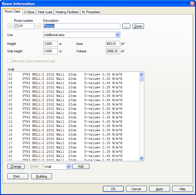
When you have selected the correct roof, you will see a list of all the building objects that have been defined so far. Here all the external walls, floor and roof will be displayed, and you can set the storey height.
Storey information. Building objects and storey height .
You can double-click on any object to edit.
Now you can start room definition. Find the room with the largest room number, and work downwards. DDS-CAD will number the rooms automatically descending. If the room is rectangular, point and click on the diagonals for the room and then press the Enter button. If the room has more corners, click on each single corner until the room has got a closed contour. In addition to the room number and shape you can also enter information about temperature and infiltration factor for the rooms. You can edit the rooms anytime by clicking the right mouse button on the room in the product database, copy and change properties. See video of the definition of a polygonal room plus a rectangular room, where room type (descriptions reads "Education") , temperature (set to 19 degrees) and infiltration factor (air exchange is set to 0.15 exchanges per hour) is set.
When all rooms have been defined, you can insert windows and doors. As for the windows, it is important to know the U value, height and sill height. Sill height is the distance from floor to lower edge window. If you tick off the option "Enter width by insertion" you can point and click on each side of the window. You can do the same with doors. See video of inserting a window with an U value of 1.8, sill height of 0.1 meter and height 2.8 meter.
Doors are inserted in the same manner as windows. See video
Do likewise until all rooms and all doors and windows are positioned in all storeys. You can check object properties in your model any time, either by double clicking on the object directly in the model, or do this via Room List.
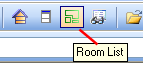
In the room list all rooms defined in the current floor are listed. At the top of the list you will find "Building", displaying all building objects in the storey - i.e. all external walls with appurtenant windows and doors, including floor and roof.
Room List. "Building" with information about the storey on top.
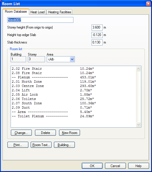
Double-click on the room or Building to see the details
Room data for the storey. All external walls with windows and doors, including floor and roof are found in this list.
See video how to change floor type for the whole storey
At last, set the design external temperature for heat loss. Select the location from the Building dialog, or set the temperature yourself. All storeys are listed in the Building dialog. All drawings created in your project will be listed here. If you have drawings you do not want to include in the heat requirement calculation, select and delete them. They will not be deleted from your project, only from the storey list. See video how to delete drawings not to be calculated, and to set the place to Oslo.
Now you can calculate the building. Open the Building dialog, select the flag for Heat requirement and press Calculate. The result will appear shortly.
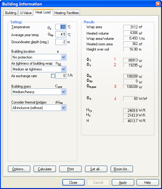
Heat requirement calculation. Qt (1) is the sum of the transmission loss, Ql(2) is the sum of the infiltration loss, Qn(3) is the sum of Qt and Ql, while Qs(4) is the specific heat requirement for the whole building (Watt/square meter)
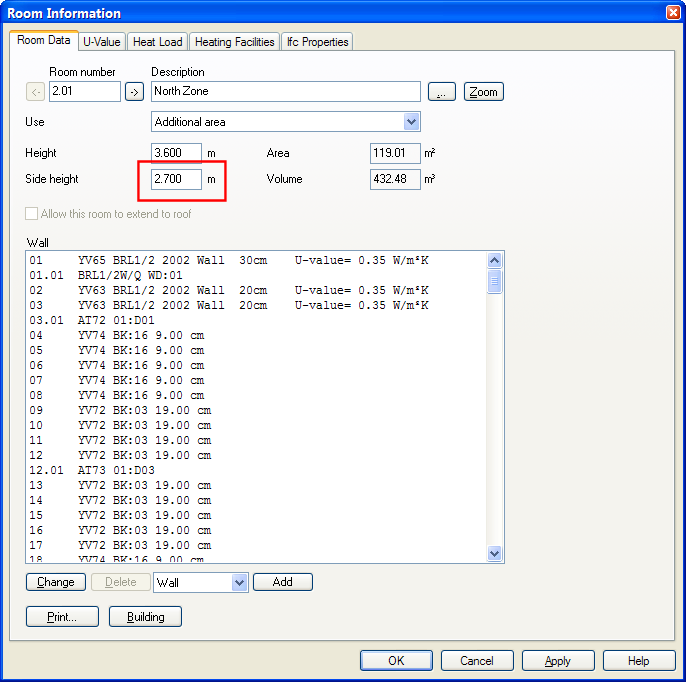
To check the result, enter into any room to see which building objects are losing heat to the environment. From the Room List you can double-click on a room to see the results.
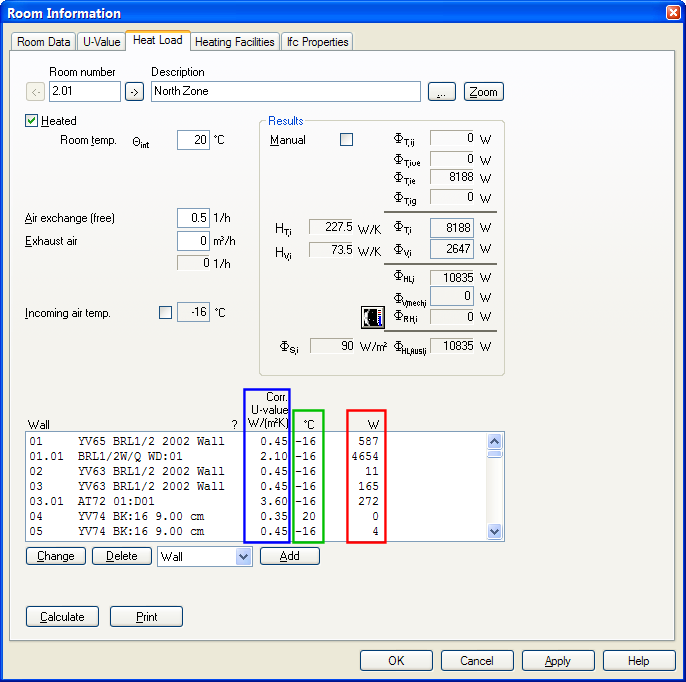
The thermal loss of a room. Temperature, infiltration etc. you will find here. In the list of building objects the blue column is the U value, green column is delta K (difference in temperature inside and outside, while the red column is the transmission loss through the object.
See video how to check heat loss for a room.
You can make a report of the calculation. Select the flag Heat requirement from the Building dialog and find the button "Print". Select the report HRN_Heat requirement_project.rpt
See video to make a report.
Click to see a video
If you get a revised architectural basis where rooms have been changed, there are two ways of updating this. One is to delete the room to defined a new one, the other is to use Move Area to move walls. In most cases you are recommended to delete the room and define a new one. If you select a wall and delete it, the entire room will disappear. See video how to delete a room and define a new one.
Thermal bridges must be inserted manually. This means that you must define the bridges after having defined the room. Each wall gets an individual number. By double-clicking on the number, you can change the wall properties.
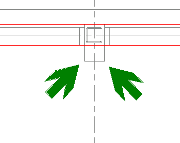
If you define the corners of a thermal bridge, you can change properties later for the wall the thermal bridge belongs to.
See video how to define a thermal bridge.
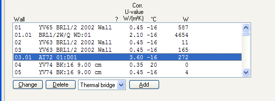
After the heat requirement calculation we can see the thermal loss through a thermal bridge.
After having finished the calculation you can print a report. Select the button "Print" from the dialog box and select the current report setup.
See example of a report.
< Previous Chapter - Next Chapter >